Overview
This page describes how to wire a PN532 NFC reader/writer module to a Seeed Studio XIAO-ESP32-C3 microcontroller so it can be used as a companion NFC tag reader/writer. The two boards communicate over I²C using only four wires.
Parts Needed
- Seeed Studio XIAO-ESP32-C3 (or pin-compatible XIAO board)
- PN532 NFC module (the red 4.3 × 4.1 cm board)
- Four jumper wires
- USB-C cable for power and flashing
See the parts list for direct Amazon links and pricing.
Connections
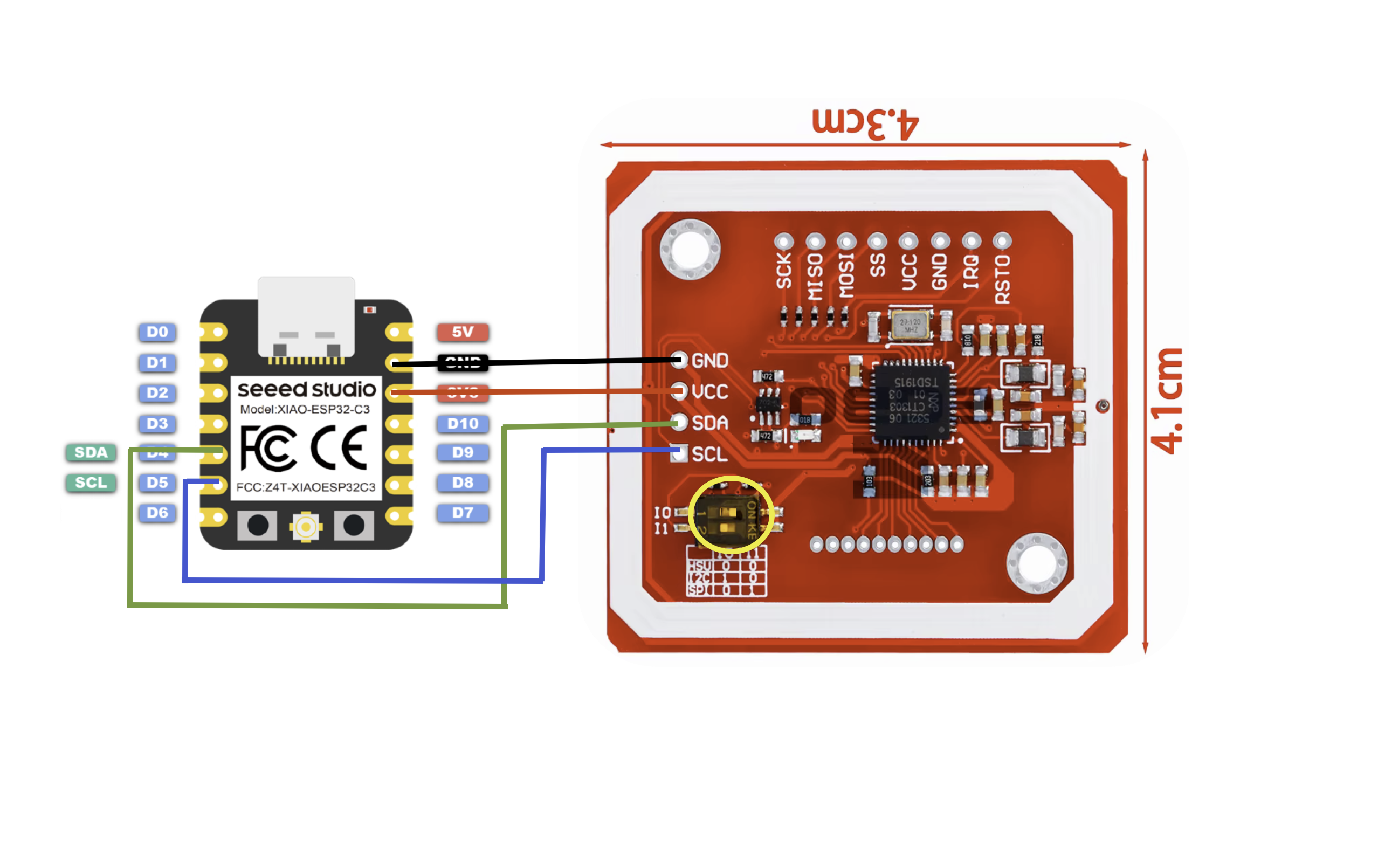
Connect the four pins between the XIAO and the PN532 as follows:
| Wire | XIAO-ESP32-C3 | PN532 | Purpose |
|---|---|---|---|
| Black | GND | GND | Ground |
| Red | 3.3V | VCC | Power |
| Green | D4 (SDA) | SDA | I²C data |
| Blue | D5 (SCL) | SCL | I²C clock |
DIP Switch Configuration
The PN532 module supports three interface modes — UART, I²C, and SPI — selected by a pair of DIP switches near the bottom edge of the board (highlighted by the yellow circle in the diagram). The silkscreen legend next to the switches reads:
RSU— UART (HSU)I2C— I²CSP— SPI
For this build the module must be set to I²C mode:
| Switch | Position |
|---|---|
| 1 (I0) | ON |
| 2 (I1) | OFF |
Assembly Tips
- Set the DIP switches to I²C mode before soldering or plugging anything in. The DIP switches seem to be covered with some sort of soft conformal coating. It isn't necessary to remove this, although you can if desired. I suggest using a straight pin, unfolded paper clip or other stiff wire to simply nudge the DIP switch into the correct position — the coating will flex to allow this and you leave the coating intact.
- Solder header pins (if used) to the four labeled pads on the PN532 (GND, VCC, SDA, SCL) and to the matching pins on the XIAO.
- Connect the four jumper wires as shown in the diagram.
- Power the XIAO from USB-C. The PN532's onboard LED should light up.
- Flash your firmware and bring an NFC tag near the antenna side of the PN532 to confirm it reads.
Once everything works on the bench, see the enclosure page for a 3D-printable case to house the build.
Firmware
The XIAO ESP32-C3 runs a small Arduino sketch that reads/writes MIFARE Classic tags via the PN532 and exposes the operations to the iPhone over BLE using the Nordic UART Service.
Download NFC-SEED-ESP32C3.inoLoading the sketch in the Arduino IDE
- Install the Arduino IDE (2.x is recommended).
- Add ESP32 board support: Arduino IDE → Settings (or File → Preferences on Windows/Linux), and paste
https://espressif.github.io/arduino-esp32/package_esp32_index.jsoninto Additional Boards Manager URLs. - Open Tools → Board → Boards Manager, search for esp32, and install esp32 by Espressif Systems (2.0.14 or newer).
- Select Tools → Board → ESP32 Arduino → XIAO_ESP32C3, then enable Tools → USB CDC On Boot → Enabled so serial logging works over USB.
- Open Tools → Manage Libraries and install:
- NimBLE-Arduino (v2.x) — the BLE stack
- PN532 by Elechouse — install both PN532 (core) and PN532_I2C (I²C HAL) from the same package. The Adafruit PN532 library's I²C path is unreliable on ESP32; the Elechouse library is the known-good choice.
- Download the sketch above and open it with File → Open. The Arduino IDE will offer to move it into a folder of the same name — accept.
- Plug the XIAO ESP32-C3 into your computer with a USB-C cable, then pick it under Tools → Port.
- Click Upload (the right-arrow button). After flashing, open the Serial Monitor at 115200 baud to confirm the PN532 initializes and BLE starts advertising.
- Install ESP32 by Espressif Systems v3.0.0 or newer (built on ESP-IDF 5.1+). The 2.0.x line predates C6 support.
- Select Tools → Board → ESP32 Arduino → XIAO_ESP32C6.
- The USB CDC On Boot menu item doesn't apply — the C6 uses native USB-Serial/JTAG and serial-over-USB is on by default.
- The C6's max BLE TX power is +20 dBm vs. +9 dBm on the C3. The sketch's
setPower(9)still works; raise it if you want extra range.
Nordic NUS Commands
Once the sketch is running, the bridge advertises as NFC-BLE-Bridge over the Nordic UART Service (NUS). Each command is a single ASCII line written to the RX characteristic and terminated with \n (or \r). Replies are returned as one or more notifications on the TX characteristic, ending with a lone \n notification that marks end-of-message. Commands are case-insensitive; arguments are not. The sketch echoes every command and reply over USB serial at 115200 baud as well, so you can drive it from a serial terminal for testing.
| Command | Description | Reply |
|---|---|---|
SCAN |
Look for an ISO-14443A tag in the field and report its UID. | OK UID:<hex> or ERR No tag found |
READ <block> |
Authenticate with the current key/mode and read one 16-byte block (0–63 on a 1K, 0–255 on a 4K). | OK B<n>:<32-hex> or ERR Auth failed block <n> / ERR Read failed block <n> |
WRITE <block> <32 hex> |
Write 16 bytes (32 hex chars) to a non-trailer block. Sector trailers are rejected to avoid bricking the sector. | OK Written block <n> or ERR ... |
DUMP |
Read every block on the tag, sector by sector, streaming one notification per block. Long-running — send CANCEL to abort. |
OK DUMP START UID:<hex>, then B<n>:<32-hex> per block, then OK DUMP END (or ERR DUMP cancelled) |
KEYA <12 hex> |
Set the 6-byte MIFARE Classic Key A used by subsequent reads/writes when AUTHMODE is A. Defaults to FFFFFFFFFFFF. |
OK Key set:<hex> |
KEYB <12 hex> |
Set the 6-byte Key B used when AUTHMODE is B. |
OK Key set:<hex> |
AUTHMODE A | AUTHMODE B |
Choose which key (and matching auth command) is used for the next operation. Defaults to A. |
OK AUTHMODE:A or OK AUTHMODE:B |
CANCEL |
Abort the in-flight long-running command (currently only DUMP). Handled directly by the BLE callback so it works while another command is still running. |
OK Cancelling or ERR Nothing to cancel |
ERR Busy instead of queuing it. Wait for the trailing \n notification (or send CANCEL) before issuing the next line. Unknown commands return ERR Unknown command: <input>.
Troubleshooting with a Generic BLE Utility
If something isn't working it's often useful to talk to the reader/writer directly — bypassing the QBox NFC Tagger app entirely — so you can tell whether the issue is in the firmware, the BLE link, or the app. Any iOS app that can connect to a Nordic UART Service (NUS) peripheral and send/receive raw text will do. Three popular free ones from the App Store:
- nRF Connect for Mobile by Nordic Semiconductor — the most thorough. Shows every advertisement packet, GATT service, and characteristic.
- Bluefruit Connect by Adafruit — has a built-in UART console mode that pairs cleanly with NUS peripherals.
- LightBlue by PunchThrough — lightweight browser; lets you write hex/UTF-8 to any characteristic and subscribe to notifications.
What to check first
- Is it advertising? Open the scanner in your chosen app and look for a peripheral named
NFC-BLE-Bridge. If you don't see it, the sketch isn't running, the LED-pin loop never reachedsetup(), or BLE init failed (3-pulse blink code). - Does the NUS service show up? Connect and look for service UUID
6E400001-B5A3-F393-E0A9-E50E24DCCA9Ewith two characteristics — RX...0002...(write) and TX...0003...(notify). - Subscribe to TX notifications on the
...0003...characteristic before sending anything. Without this you'll send a command, the reader will respond, and you'll see nothing — making it look broken when it's working.
Bluefruit Connect (easiest)
- Open the app, tap
NFC-BLE-Bridge, then choose UART. - Type
SCANand tap Send. Make sure the line ending is set to \n (Newline) in the gear menu — the sketch only dispatches a command after it sees a newline or carriage return. - Place a tag on the antenna and you should see
OK UID:<hex>. No tag, and you'll seeERR No tag foundafter about a second.
nRF Connect / LightBlue (more manual)
- Connect to
NFC-BLE-Bridge, expand the NUS service. - On the TX characteristic (
...0003...) tap the subscribe / notifications icon (three down-arrows in nRF Connect, the Listen for notifications button in LightBlue). - On the RX characteristic (
...0002...) write the bytes forSCAN\n. In nRF Connect choose Text input and typeSCAN\nwith the literal backslash-n; in LightBlue switch the input to UTF-8 String and append a real newline. If you forget the terminator, nothing happens — the bridge is waiting for end-of-line. - The reply arrives as several short notifications (≤ 20 bytes each) followed by a final lone
\n. Concatenate them to read the response.
USB serial fallback
You can also skip BLE entirely: open the Arduino IDE Serial Monitor at 115200 baud with line ending set to Newline. Every BLE command and reply is mirrored on USB serial, and you can issue commands the same way. If the reader/writer works over USB but not BLE, the problem is on the radio side; if it doesn't work over either, focus on the PN532 wiring and DIP switches.
Need Help?
If something isn't working, please open an issue on the project's GitHub page or visit the support page.